Modify the Alesis 3630 comp/gate for switching and bypass in a guitar amplifier setup.
Alesis 3630 compressor mod:
Turn a stereo compressor into a
dual gate/comp with remote switching.
Parts:
-2 relays 9VDC
-4 diodes
-2 resistors 65k
-DC adaptor chassis mount jack.
First you need to open up the 3630. The rack wings come off,
the back cover un-screws, and the plastic nuts come off the input and output
jacks.
Remove all of the PC board jacks. Mark where each jack was,
the names are also labeled on the back cover. In case you miss the labelling
step.
I found the output and input jacks on compressor B side were
the best to use for signal in and out.
The two compressors will be switched internally.
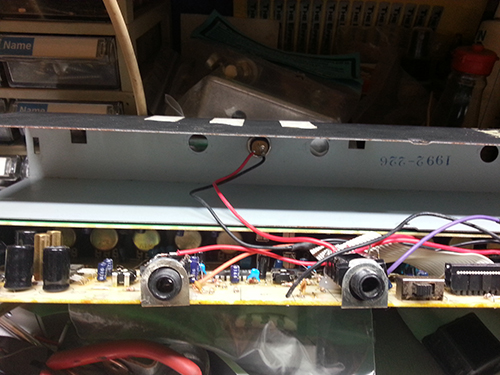
Once all the jacks are removed. Make four jumper wires about
2cm long each to connect the side chain jacks. As they were when the jacks were
installed. (Photo)
The first relay is to be put in between the in/out jacks.
In/out signal on the first set, comp A in out on the next set, and comp B is on
the 3rd set. The voltage switch pins should be ready to solder now.
Comp A and B are switch able in position, this mod has B
comp being the normal open relay comp, and A is the switched comp. However
order is not relevant, they are entirely out of the signal path when switched.

The relay needs power and the flywheel diode. Red wire on
the left side, black on right. (photo 2)

The diode is used to catch voltages and to reduce electronic
noise. (photo diode)

The 1st set of relay pins will go to the in/out
jacks. Also connect the ground pin on the jacks to ground. A short black wire
2cm long should solder on, and go into the hole on the PCB. At this point the 2
resistors are soldered between the + lug and ground on each ¼” jack. These
resistors help disperse stray DC voltage. (photo)

Next you need to bypass the entire rig, so we may have
bypass, and two switchable comp/gates. (photo)

Each relay is attached to the FTSW jacks (photo)

Attach the DC jack into the cover labeled “sidechain” in the
middle of the FTSW section, send –DC voltage(black wire) to ground. This DC
jack is plastic but metal or plastic doesn’t matter, and use enough wire to be
able to remove the cover and sit up top the unit out of the way to continue
your work. Wires will tuck under the upper PCB in final assembly. Negative tip
was used, as most pedal 9volt adaptors come in this fashion. The polarity is
put back to normal inside anyways (the same goes for inside effect pedals,
BTW!). (photo)
Negative pin connects to the two relays, keep the diode
soldered on also. The DC negative voltage also needs to go to ground. Utilize
the sidechain ground jack hole in PCB for this. The positive wire comes from
the DC jack into the ground on the FTSW jacks. On the tip of the FTSW jacks
solder a diode, connected to the relay wire (prevents voltage cross talk, and
dual relay triggering)
Then solder a positive voltage to the two
relays.
The Dual/Comp/Gate project is done. Ready to wrap it up. The
jacks were put into the soldered on PCB jack holders, and then a bit of hot
glue into the back side and cracks hold them in place. Try to center them as best
you can. The DC voltage jack is bolted in the chassis cover. Flip the back
cover down, and place onto the unit and PCB’s, make sure each jack pops through
its own place easily. Attach the rack wings. Put the nuts back on the jacks. Be
sure to label the 9VDC and the FTSW jacks. Input an Output should have been in
the original spots anyway and are already labelled.
The Alesis 3630 is also a 9 (nine) volt alternating current
power. 9VAC this is different from 9VDC, YES, there is a difference, and there
are reasons why things are built like this.
IMPORTANT: Be sure to label the 9VDC and do not connect 9VAC
to it. The relay units cannot be powered by the 9VAC. A voltage conversion
circuit could be built to convert relay power inside the 3630 into the required
DC voltage 9V or 5V. This story was not about building 7809 or 7805 IC power
conversion systems. There also may be other units inside a rack that require
9VDC. SO an additional power source may be useful. (photo)
Get ready to connect the way you like. This 3630 is happily
sitting in the effects loop of a popular amplifier. As well as a classic ZOOM
multi effect and midi volume control. The comp is set on no comp, and the gate
is set to clamp down very light on any amp noise, when the guitar volume is
down. Comp A is set for no comp but heavy tight gate for high gain channel and
it is set for when the guitar volume is down.
Here is the Youtube video link to further view the modified 3630 in action, as well as an explaination of the new features.

Comments
Post a Comment